- inputThe input mesh that needs to be converted to tetrahedral elements.
C++ Type:MeshGeneratorName
Controllable:No
Description:The input mesh that needs to be converted to tetrahedral elements.
ElementsToTetrahedronsConverter
This ElementsToTetrahedronsConverter object is designed to convert all the elements in a 3D mesh consisting only linear elements into TET4 elements.
Overview
The ElementsToTetrahedronsConverter converts a 3D mesh that consists of first-order elements (e.g., TET4, PYRAMID5, PRISM6, and HEX8) into a mesh that only contains TET4 elements.
Methods
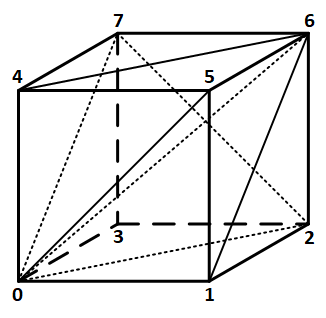
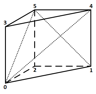
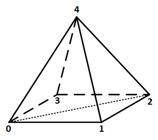
All original mesh elements which are not TET4 type are converted into TET4 elements through splitting by this mesh generator. To be specific, each HEX8 element is split into six TET4 elements; each PRISM6 element is split into three TET4 elements; and each PYRAMID5 element is split into two TET4 elements. Details on the splitting approach follow.

Figure 1: An example of splitting of a HEX8 element into six TET4 elements.

Figure 2: An example of splitting of a PRISM6 element into three TET4 elements.

Figure 3: An example of splitting of a PYRAMID5 element into two TET4 elements.
After this conversion, all the elements become TET4 elements. In that case, all the subdomain IDs and names can be preserved.
Splitting of HEX8 Elements
There are multiple ways to split one HEX8 element into multiple TET4 elements, resulting in either five or six TET4 elements (or even more if additional nodes can be added). A splitting method that does not require adding nodes needs to split each of the six quadrilateral faces of a HEX8 element into two triangles, which can be done in two different ways for each face. As these quadrilateral faces could be shared with neighboring HEX8 or other types of elements, the splitting of the quadrilateral faces on neighboring elements must be performed consistently. To achieve a consistent splitting approach, which will be discussed later in this documentation page, a HEX8 element needs to be split into six TET4 elements. An example of this splitting is illustrated in Figure 1. Note that the splitting approach shown in Figure 1 is not unique and will be discussed later.
Splitting of PRISM6 Elements
A PRISM6 element can be split into three TET4 elements. An example of this splitting is illustrated in Figure 2. Note that the splitting approach shown in Figure 2 is not unique and will be discussed later. Namely, the three quadrilateral faces of a PRISM6 element need to be split consistently with the neighboring elements.
Splitting of PYRAMID5 Elements
A PYRAMID5 element can be split into two TET4 elements. An example of this splitting is illustrated in Figure 3. Note that the splitting approach shown in Figure 3 is not unique and will be discussed later. Namely, the one quadrilateral face of a PYRAMID5 element needs to be split consistently with the neighboring elements.
Consistent Splitting for Neighboring Elements
As discussed above, although splitting of non-TET elements into TET4 elements is not unique, it is crucial to ensure that the splitting of the neighboring elements involves consistent splitting of the quadrilateral faces. To achieve this, the following approach is used. For each quadrilateral face, there are two ways to split it into two triangles, which correspond to the two diagonal lines of the quadrilateral face. Therefore, in order to ensure that one of the two diagonal lines is selected consistently for all the elements, the diagonal line that involves the node with the lowest global node ID among the four nodes of the quadrilateral face is selected.
Example Syntax
[Mesh<<<{"href": "../../syntax/Mesh/index.html"}>>>]
  [convert]
    type = ElementsToTetrahedronsConverter<<<{"description": "This ElementsToTetrahedronsConverter object is designed to convert all the elements in a 3D mesh consisting only linear elements into TET4 elements.", "href": "ElementsToTetrahedronsConverter.html"}>>>
    input<<<{"description": "The input mesh that needs to be converted to tetrahedral elements."}>>> = block_1
  []
[]Input Parameters
- enableTrueSet the enabled status of the MooseObject.
Default:True
C++ Type:bool
Controllable:No
Description:Set the enabled status of the MooseObject.
- save_with_nameKeep the mesh from this mesh generator in memory with the name specified
C++ Type:std::string
Controllable:No
Description:Keep the mesh from this mesh generator in memory with the name specified
Advanced Parameters
- nemesisFalseWhether or not to output the mesh file in the nemesisformat (only if output = true)
Default:False
C++ Type:bool
Controllable:No
Description:Whether or not to output the mesh file in the nemesisformat (only if output = true)
- outputFalseWhether or not to output the mesh file after generating the mesh
Default:False
C++ Type:bool
Controllable:No
Description:Whether or not to output the mesh file after generating the mesh
- show_infoFalseWhether or not to show mesh info after generating the mesh (bounding box, element types, sidesets, nodesets, subdomains, etc)
Default:False
C++ Type:bool
Controllable:No
Description:Whether or not to show mesh info after generating the mesh (bounding box, element types, sidesets, nodesets, subdomains, etc)